
Each node is a source or destination for information
Requires ports to physical interface
Can use Fiber or Copper as Media
Fiber Domains
Are Dynamically Assigned
Have a principal switch election similar to Spanning Tree
Switch finds N port addresses
Assigns FC ID to the Node
Whenever a change takes place in the name server database, the fabric
controller sends a Registered State Change Notification (RSCN) to all the nodes
impacted by the change. If zoning is not configured, the fabric controller
sends an RSCN to all the nodes in the fabric.
DCBX protocol is a discovery and capability exchange protocol, which helps Converged Enhanced Ethernet devices to convey and configure their features with the other CEE devices in the network. DCBX is used to negotiate capabilities between the switches and the adapters, and it allows the switch to distribute the configuration values to all the attached adapters. This helps to ensure consistent configuration across the entire network
DCBX protocol is a discovery and capability exchange protocol, which helps Converged Enhanced Ethernet devices to convey and configure their features with the other CEE devices in the network. DCBX is used to negotiate capabilities between the switches and the adapters, and it allows the switch to distribute the configuration values to all the attached adapters. This helps to ensure consistent configuration across the entire network


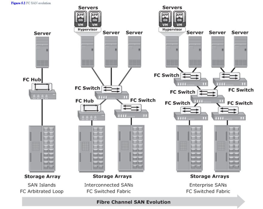
Hubs are used as communication devices in FC-AL implementations. Hubs physically connect nodes in a logical loop or a physical star topology. All the nodes must share the loop because data travels through all the connection points. Because of the availability of low-cost and high-performance switches, hubs are no longer used in FC SANs.
Switches are more intelligent than hubs and directly route data from one physical port to another. Therefore, nodes do not share the bandwidth. Instead, each node has a dedicated communication path.
Switches are available with a fixed port count or with modular design. In a modular switch, the port count is increased by installing additional port cards to open slots. The architecture of a director is always modular, and its port count is increased by inserting additional line cards or blades to the director's chassis. High-end switches and directors contain redundant components to provide high availability. Both switches and directors have management ports (Ethernet or serial) for connectivity to SAN management servers.
A port card or blade has multiple ports for connecting nodes and other FC switches. Typically, a Fibre Channel transceiver is installed at each port slot that houses the transmit (Tx) and receive (Rx) link. In a transceiver, the Tx and Rx links share common circuitry. Transceivers inside a port card are connected to an application specific integrated circuit, also called port ASIC. Blades in a director usually have more than one ASIC for higher throughput
FC Switch Versus FC Hub
Scalability and performance are the primary differences between switches and hubs. Addressing in a switched fabric supports more than 15 million nodes within the fabric, whereas the FC-AL implemented in hubs supports only a maximum of 126 nodes.
Fabric switches provide full bandwidth between multiple pairs of ports in a fabric, resulting in a scalable architecture that supports multiple simultaneous communications.
Hubs support only one communication at a time. They provide a low-cost connectivity expansion solution. Switches, conversely, can be used to build dynamic, high-performance fabrics through which multiple communications can take place simultaneously. Switches are more expensive than hubs.
FC Connectivity
Point to Point: Simplest connection. Two devices are directly connected.
Arbitrated Loop: Much like token ring. Only one device can operate at a time. They contend for the media and arbitrate to gain control of the loop.
Switched Fabric: In a switched fabric, the link between any two switches is called an Interswitch link (ISL). ISLs enable switches to be connected together to form a single, larger fabric. ISLs are used to transfer host-to-storage data and fabric management traffic from one switch to another. By using ISLs, a switched fabric can be expanded to connect a large number of nodes.
Fiber Channel Ports:
- N_Port: An end point in the fabric. This port is also known as the node port. Typically, it is a host port (HBA) or a storage array port connected to a switch in a switched fabric.
- E_Port: A port that forms the connection between two FC switches. This port is also known as the expansion port. The E_Port on an FC switch connects to the E_Port of another FC switch in the fabric through ISLs.
- F_Port: A port on a switch that connects an N_Port. It is also known as a fabric port.
- G_Port: A generic port on a switch that can operate as an E_Port or an F_Port and determines its functionality automatically during initialization.

Zoning: Zoning is an FC switch function that enables
node ports within the fabric to be logically segmented into groups and
to communicate with each other within the group. Whenever a change takes place in the name server database, the fabric
controller sends a Registered State Change Notification (RSCN) to all
the nodes impacted by the change. If zoning is not configured, the
fabric controller sends an RSCN to all the nodes in the fabric.
Involving the nodes that are not impacted by the change results in
increased fabric-management traffic. For a large fabric, the amount of
FC traffic generated due to this process can be significant and might
impact the host-to-storage data traffic. Zoning helps to limit the
number of RSCNs in a fabric. In the presence of zoning, a fabric sends
the RSCN to only those nodes in a zone where the change has occurred.
A port or node can be a member of multiple zones. Nodes distributed
across multiple switches in a switched fabric may also be grouped into
the same zone. Zone sets are also referred to as zone configurations.
Zoning can be categorized into three types:
- Port zoning: Uses the physical address of switch ports to define zones. In port zoning, access to node is determined by the physical switch port to which a node is connected. The zone members are the port identifier (switch domain ID and port number) to which HBA and its targets (storage devices) are connected. If a node is moved to another switch port in the fabric, then zoning must be modified to allow the node, in its new port, to participate in its original zone. However, if an HBA or storage device port fails, an administrator just has to replace the failed device without changing the zoning configuration.
- WWN zoning: Uses World Wide Names to define zones. The zone members are the unique WWN addresses of the HBA and its targets (storage devices). A major advantage of WWN zoning is its flexibility. WWN zoning allows nodes to be moved to another switch port in the fabric and maintain connectivity to its zone partners without having to modify the zone configuration. This is possible because the WWN is static to the node port.
- Mixed zoning: Combines the qualities of both WWN zoning and port zoning. Using mixed zoning enables a specific node port to be tied to the WWN of another node.
Virtual SAN (also called virtual fabric)
is a logical fabric on an FC SAN, which enables communication among a
group of nodes regardless of their physical location in the fabric. In a
VSAN, a group of hosts or storage ports communicate with each other
using a virtual topology defined on the physical SAN. Multiple VSANs may
be created on a single physical SAN. Each VSAN acts as an independent
fabric with its own set of fabric services, such as name server, and
zoning. Fabric-related configurations in one VSAN do not affect the
traffic in another.
VSANs improve SAN
security, scalability, availability, and manageability. VSANs provide
enhanced security by isolating the sensitive data in a VSAN and by
restricting access to the resources located within that VSAN. The same
Fibre Channel address can be assigned to nodes in different VSANs, thus
increasing the fabric scalability. Events causing traffic disruptions in
one VSAN are contained within that VSAN and are not propagated to other
VSANs. VSANs facilitate an easy, flexible, and less expensive way to
manage networks. Configuring VSANs is easier and quicker compared to
building separate physical FC SANs for various node groups.
The Fabric Login Server is located at the predefined address of FFFFFE and is used during the initial part of the node's fabriclogin process.
The Name Server (formally known as Distributed Name Server) is located at the predefined address FFFFFC and is responsible for name registration and management of node ports. Each switch exchanges its Name Server information with other switches in the fabric to maintain a synchronized, distributed name service.
Each switch has a Fabric Controller located at the predefined address FFFFFD. The Fabric Controller provides services to both node ports and other switches. The Fabric Controller is responsible for managing and distributing Registered State Change Notifications (RSCNs) to the node ports registered with the Fabric Controller. If there is a change in the fabric, RSCNs are sent out by a switch to the attached node ports. The Fabric Controller also generates Switch Registered State Change Notifications (SW-RSCNs) to every other domain (switch) in the fabric. These RSCNs keep the name server up-to-date on all switches in thefabric.
FFFFFA is the Fibre Channel address for the Management Server. The Management Server is distributed to every switch within the fabric. The Management Server enables the FC SAN management software to retrieve information and administer the fabric.